


Controlled Assembly
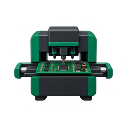
Work instructions, design revisions, material identity, first-article approval and soldering controls should connect the approved sample to the intended production configuration.

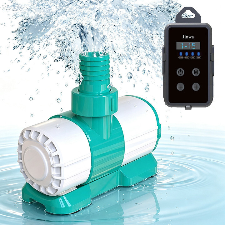
Fish Aquarium Water Pump-Energy-Efficient,Quiet,Variable Speeds,Safe.
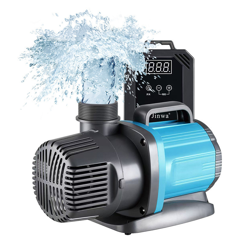
Pond Waterfall Pump with Variable Speed : High Flow & Energy Efficient.
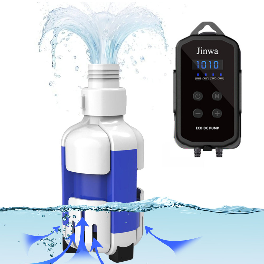
Fish Tank Pump-Energy-Efficient, Quiet,Variable Speeds,Safe DC 24V.
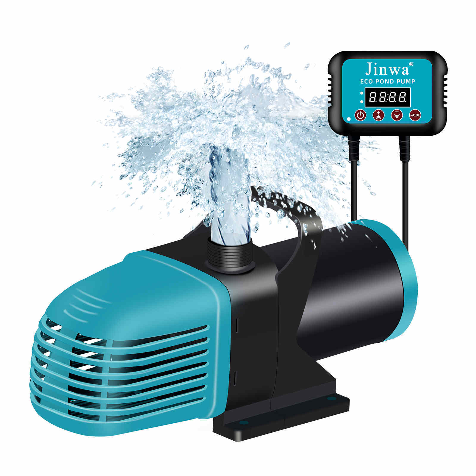
Pond Waterfall pump with Variable Speed : High Flow & Energy Efficient
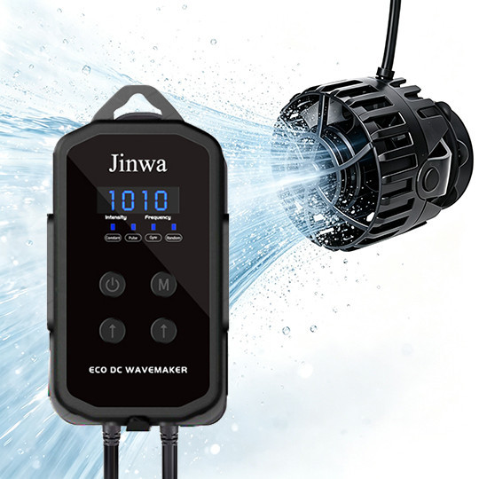
Wave Maker for Fish Tank-Quiet, Energy-Efficient,4 Modes ,Variable Speed.
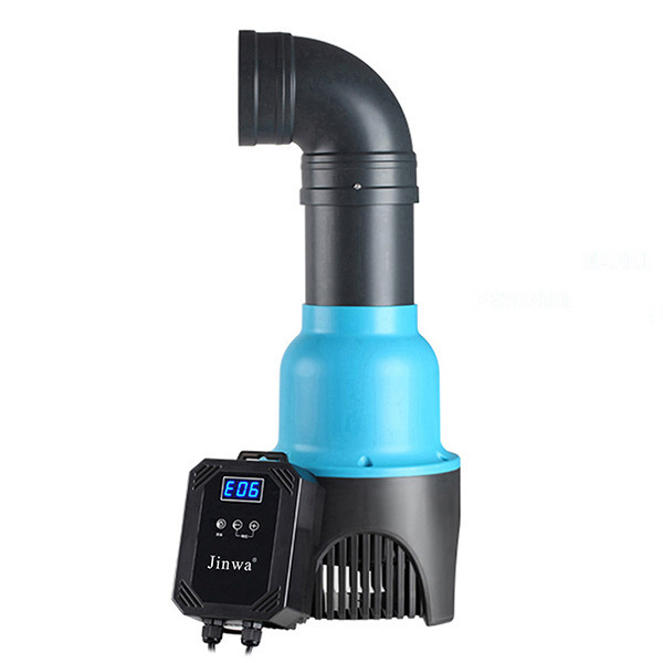
Pond Waterfall Pump with Variable Speed : High Flow & Energy Efficient.
Fish Aquarium Water Pump-Energy-Efficient,Quiet,Variable Speeds,Safe.
Pond Waterfall Pump with Variable Speed : High Flow & Energy Efficient.
Variable Speed Pond Pump
Controller Technology | Aquarium, Pond and Water-Feature Pumps
Review the controller, motor, power source, control objective, interface, environment and validation requirements before moving from sample evaluation to repeatable OEM production.
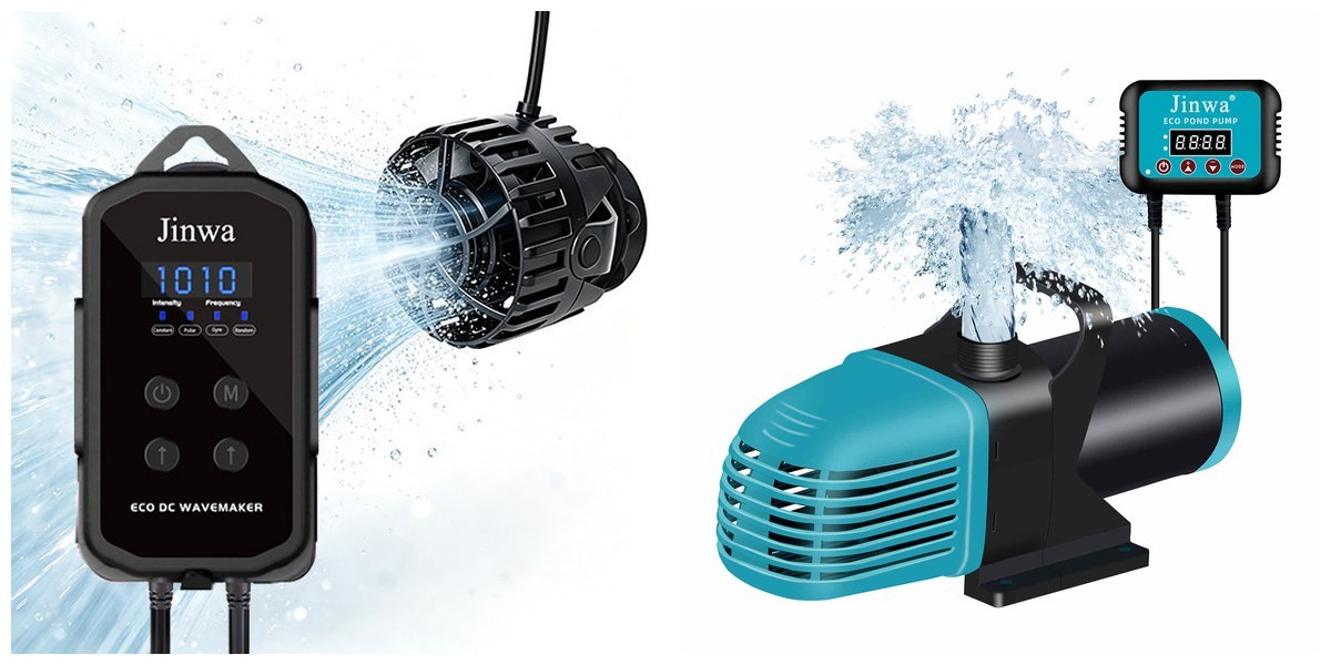
Controller Series
A pump controller must be evaluated as part of a complete system. The pump motor, hydraulic load, power source, user command, feedback method, enclosure and protection strategy must agree before a controller configuration is selected.
Jinwa's public product pages show variable-speed and variable-flow contexts across aquarium, pond and water-feature pumps. The smaller and larger controller images are representative form-factor visuals for an early project discussion; they do not establish compatibility with every pump or define a power classification.
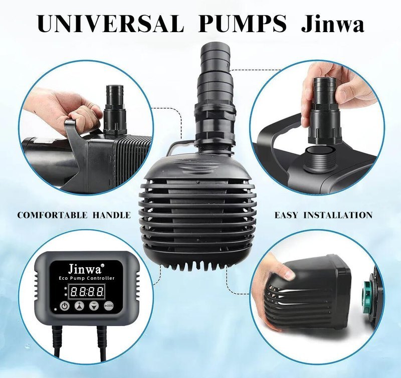
Controller Advantages
Advanced Production Line
A variable-speed pump controller program requires controlled hardware, software, assembly, test and release records. The exact process and equipment must be confirmed for the selected model and manufacturing site.

Work instructions, design revisions, material identity, first-article approval and soldering controls should connect the approved sample to the intended production configuration.
Each published test statement should connect to a fixture, acceptance criterion, raw measurement and applicable hardware, firmware and parameter revision.
Where implemented, serial records can link the product revision, configuration, material lots, process results, final test and shipment record.
This framework shows the control points a B2B buyer should review. Publish only the steps and evidence that apply to the approved Jinwa program.
Collect pump, motor, input power, control objective, environment, market and validation requirements.
Define AC or DC boundaries, external or integrated electronics, motor topology, interface and protection responsibilities.
Freeze schematics, PCB, enclosure, firmware baseline, approved materials and critical characteristics.
Confirm component identity, lot and date code, PCB revision, storage condition and structural materials.
Match work order, BOM, stencil, placement program, material lot and first-article approval.
Control the applicable printing, placement, reflow and through-hole processes, with risk-based inspection evidence.
Define the cleaning route, contamination checks, connector condition and PCBA lot or serial record.
Program the controlled build, load model parameters, record calibration and verify the written data.
Check control power, sensing, PWM or drive output, fault inputs, user interface and communication where applicable.
Apply the approved coating or potting, thermal interface, enclosure, connector and sealing controls.
Verify startup, speed range, load changes, temperature, fault strategy, safety and endurance against the project plan.
Confirm identity, firmware and parameters, test completion, serial record, packaging and shipment status.
Testing and R&D
A low-voltage external controller, an integrated motor drive and an AC-input variable-frequency drive do not share identical safety, thermal, EMC or load-test requirements. Build the validation matrix around the actual product boundary.

Verify part identity, polarity, soldering, connector placement and hidden-joint risk with the inspection method appropriate to the assembly.
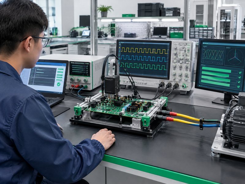
Control the firmware and parameter version, calibration values, sensing, drive outputs, communication and fault inputs before loaded-pump testing.
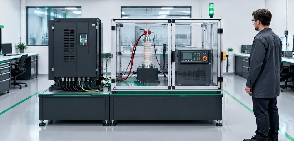
Define insulation, protective-earth, dielectric-strength, leakage, spacing and discharge tests for the actual product and target market.

Test the target motor and hydraulic load through startup, low-speed operation, load changes, power interruption and defined fault scenarios.

Set thermal limits, operating duration, sampling and final acceptance by product risk and customer requirement rather than a universal time.

Review motor parameters, startup behavior, operating range, feedback, ramps and fault states at project level. Named algorithms should be published only when verified.

Review the PCB, enclosure, connectors, thermal path, assembly sequence, test access, service strategy and controlled changes before volume release.
Services
Move from application data to a reviewable controller program with clearly defined responsibilities and evidence.
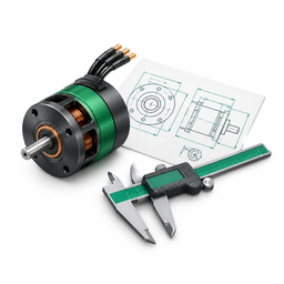
Send the pump and motor data, input power, target control behavior, installation environment, target market, sample requirement and expected volume. Final ratings, functions, interfaces, compliance scope and commercial terms remain subject to technical review.