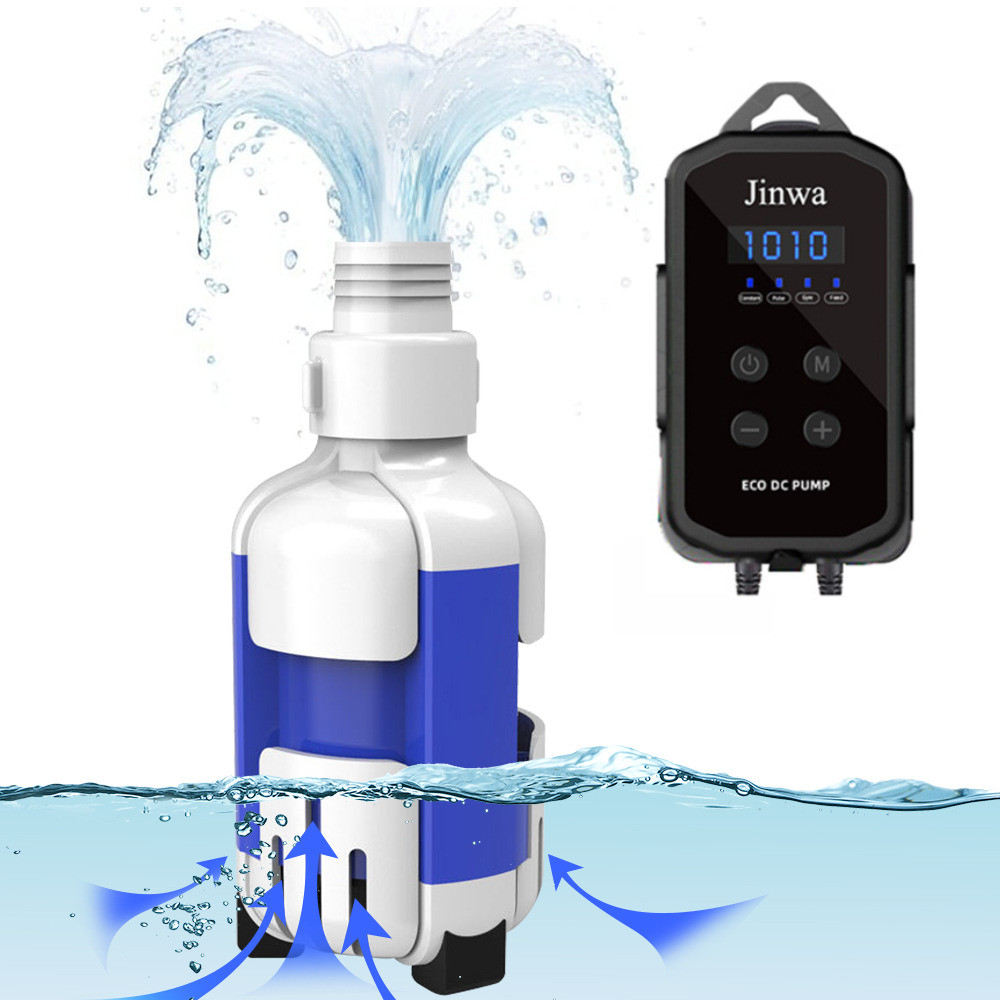
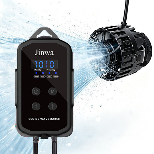
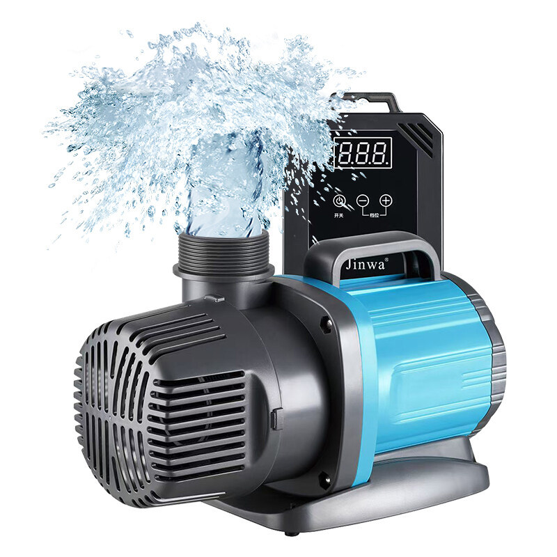
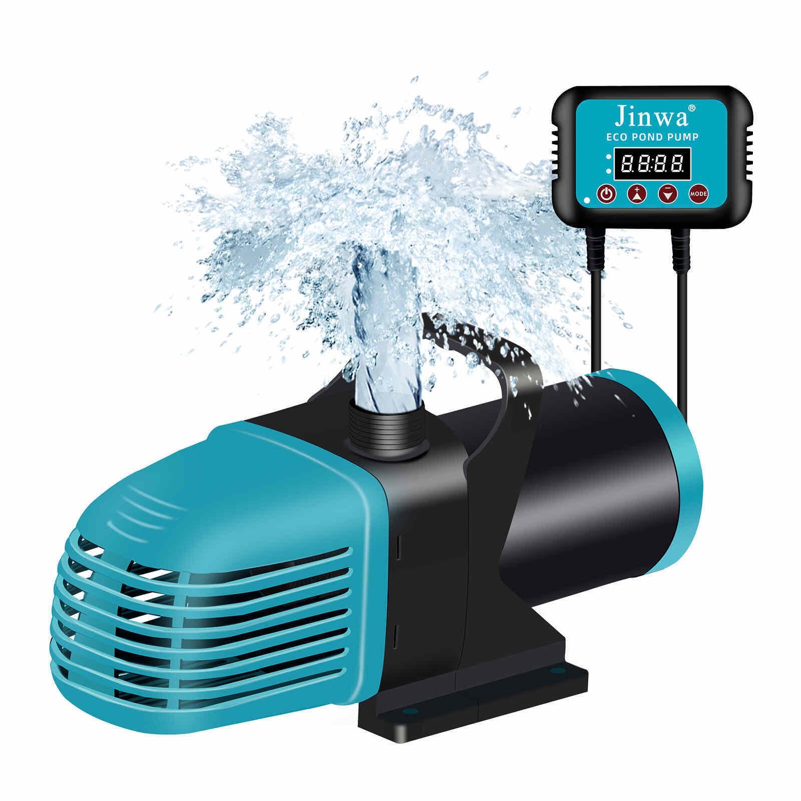

Our Vision: Global Leadership in Variable-Speed Pumps

Smarter Flow, Better Life!
Home / motor technology

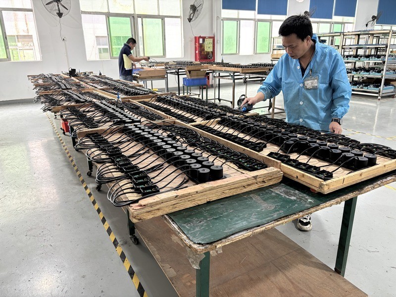
Illustrative brushless motor production team working on motor assemblies in a modern manufacturing workshop

Brushless Motor Technology | OEM/ODM Manufacturing

Brushless Motor Technology and Manufacturing Process

Jinwa develops DC and AC brushless motor solutions through a controlled path from specification review and stator winding to permanent-magnet rotor assembly, electronic commutation, balancing, end-of-line testing and traceability.

  • DC and AC brushless architectures
  • Controlled production checkpoints
  • Model-specific test planning
  • OEM/ODM engineering review

Controlled from input to release

Brushless Motor Manufacturing Process

Our process framework connects the electrical design, mechanical construction, drive electronics and quality records required for repeatable brushless motor production. The exact in-house, approved-supplier and model-dependent scope is confirmed for each program.

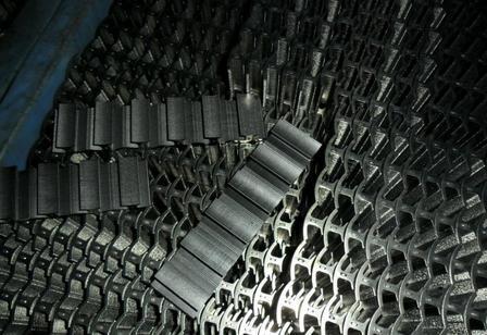
  1. Electrical steel laminations are stamped, stacked and secured to form the stator core.
    01

    Stator Core Lamination

    Stamp silicon steel sheets, stack and fasten them to form the stator core for magnetic conduction.

    Control point:Ensure stacking factor; control burr & perpendicularity; no wrong/missing sheets; material batch inspection.
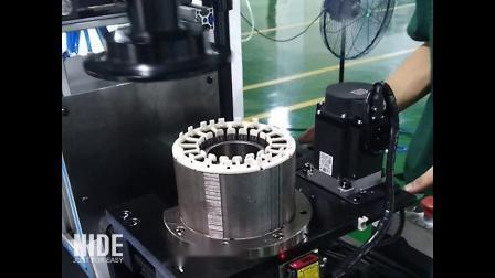
  2. Incoming inspection station with labeled brushless motor components and material lot records
    02

    Stator Insulation & Slot Paper Insertion

    Fit insulation bobbins and slot paper to separate windings from core, prevent short circuits, meet Class H insulation.

    Control point: Insulation intact and properly positioned; avoid wire enamel scratching.
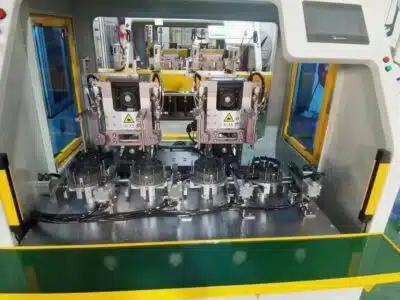
  3. Stacked electrical-steel laminations positioned in a fixture for brushless motor stator assembly
    03

    Automatic Stator Winding

    Automatic machine winds enameled wire into 3-phase windings following required turns and phase sequence.

    Control point:Correct wire gauge & turns; stable tension; balanced 3-phase resistance; coil shaping.
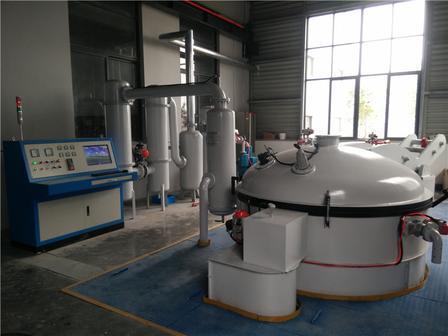
  4. Stator slot insulation being positioned before brushless motor winding
    04

    Stator Varnish Impregnation & Drying

    Vacuum impregnate stator with epoxy varnish, then oven cure to fix windings for moisture & shock resistance.

    Control point: Control vacuum, time and curing temperature; bubble-free coating; insulation resistance test.
  5. Brushless motor stator winding operation with phase leads identified for electrical inspection
    05

    Rotor Assembly

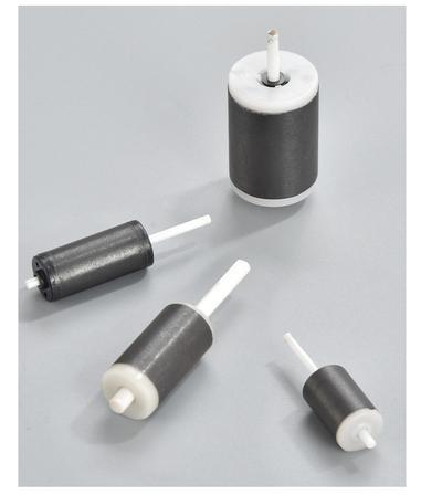
    Bond permanent magnets to rotor core and press-fit ceramic shaft to complete rotor assembly.

    Control point: Correct magnet polarity; secure adhesive; good shaft concentricity; no magnet chipping.
  6. Motor stator insulation consolidation process with batch identification and controlled material handling
    06

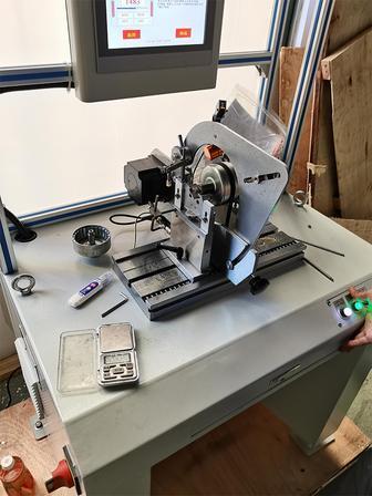
    Rotor Dynamic Balancing Correction

    Test rotor eccentricity and remove excess material to reduce vibration and noise..

    Control point: Meet balance grade; recheck after correction; avoid magnet damage.
  7. Permanent magnets positioned on a brushless motor rotor with polarity and adhesive checks
    07

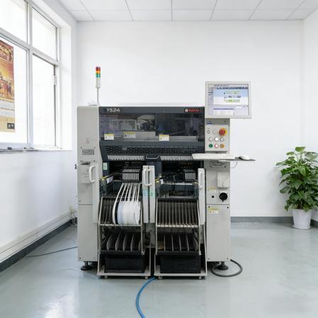
    SMT Assembly & Firmware Programming of Drive PCB

    SMT mount electronic components on PCB, solder and program sensorless FOC firmware with protection functions.

    Control point: AOI check for bad solder; confirm firmware version; pre-test protection features.
  8. Brushless motor rotor on a dynamic balancing machine beside an assembled shaft and bearing system
    08

    Soldering & Assembly of Stator to Drive Board

    Solder stator leads to drive PCB and install terminals for electrical connection.

    Control point: No cold solder joints; pass wire pull test; correct phase sequence; solder insulation protection.
  9. Brushless motor controller PCB with connector identification and firmware traceability record
    09

    Motor Final Assembly (Stator, Rotor, Housing & Seals)

    Assemble all parts and finish magnetic coupling structure to realize water-electricity separation.

    Control point: Seals fully seated; rotor rotates freely; proper screw torque & magnetic gap.
  10. Brushless motor final assembly in a fixture with shaft, connector and housing interfaces visible
    10

    Epoxy Vacuum Potting

    Vacuum epoxy potting and curing of drive cavity to achieve IP68 waterproofing.

    Control point: Complete degassing; accurate glue ratio & curing temperature; no voids; insulation retest.
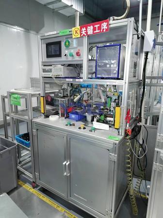
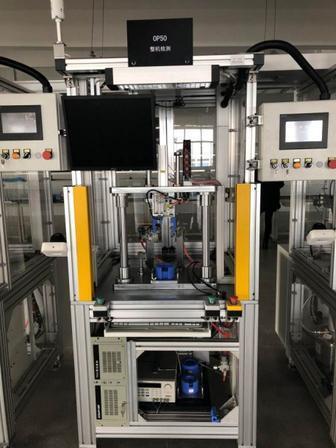
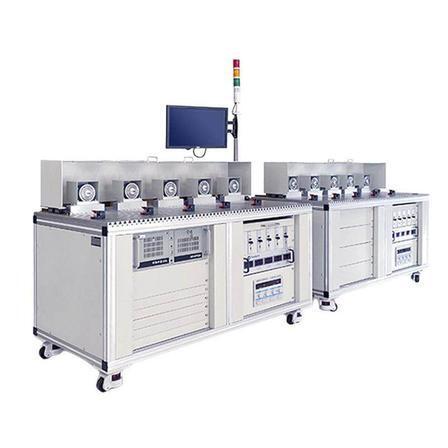
  11. End-of-line brushless motor test station measuring electrical and rotational performance
    11

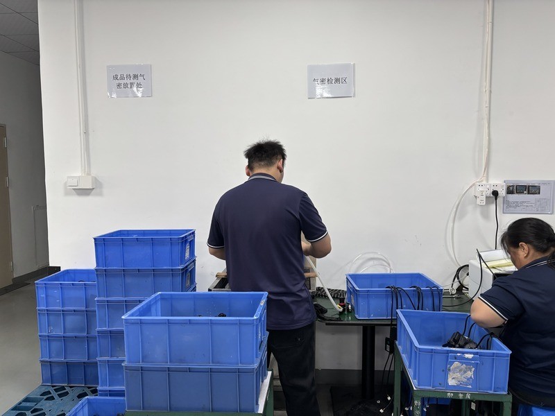
    Electrical and Performance Testing

    Power-on aging test, measure speed, current, noise, temperature rise and verify protection functions.

    Control point:Hipot test; all parameters within spec; isolate defective products.
  12. Serialized brushless motor package linked to final inspection and end-of-line test records
    12

    Final Inspection, Visual Check & Warehousing

    Visual and performance inspection, barcode recording. Pack and store qualified products.

    Control point: Check appearance & nameplate; traceability barcode input; sampling performance test.

Architecture terminology

DC and AC Brushless Motor Platforms

"Brushless motor" describes a motor-and-drive system rather than one universal electrical interface. B2B specifications should identify the input stage, winding and back-EMF design, commutation method, feedback method and controller boundary.

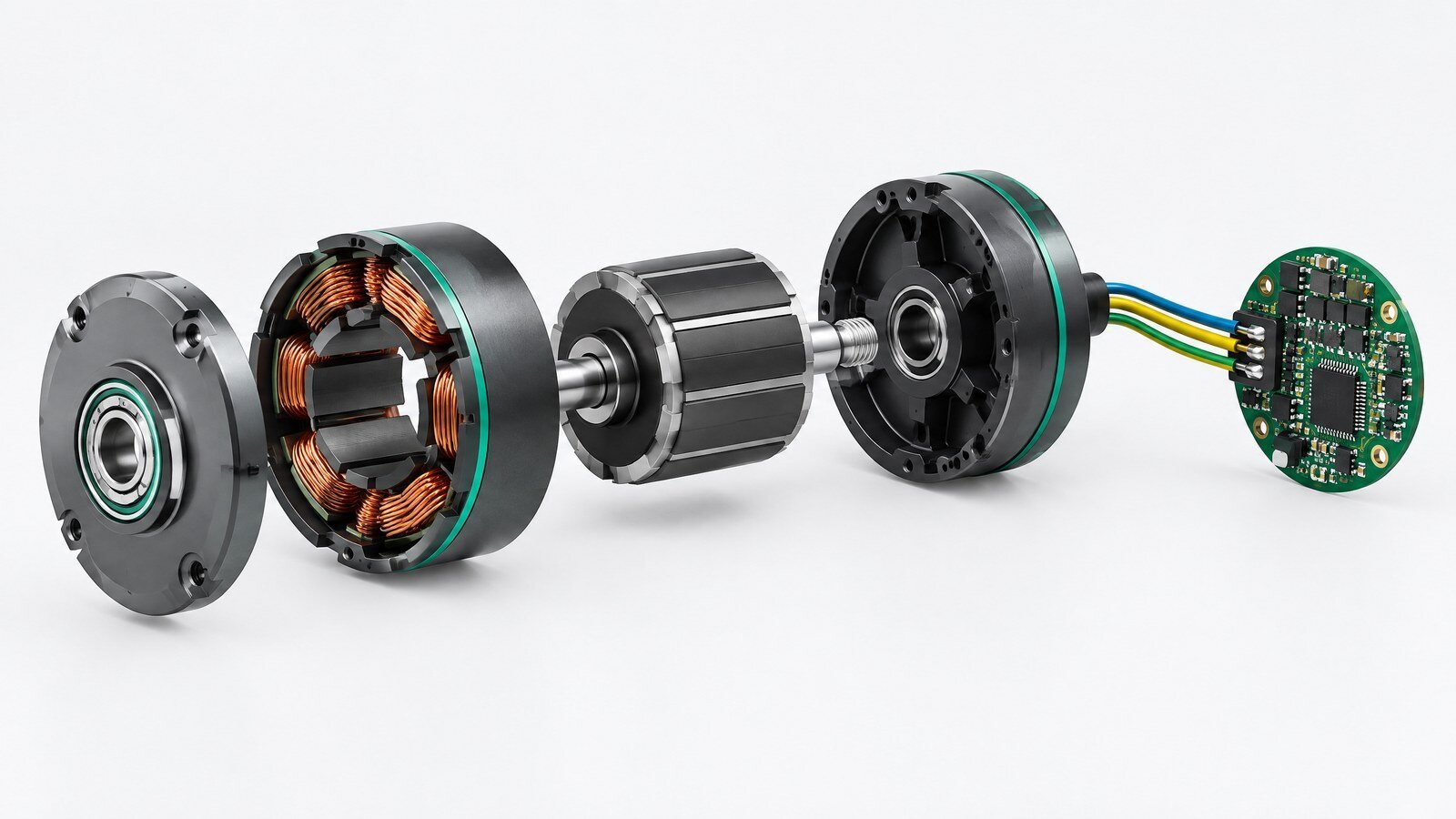
Diagram of a DC brushless motor with permanent-magnet rotor, stator windings and electronic commutation controller
DC architecture

DC Brushless Motor (BLDC)

A DC source or DC bus supplies an electronic inverter that creates controlled phase currents in the stator. BLDC systems may use Hall feedback, sensorless estimation or another position method.

  • Confirm nominal and allowable DC input range.
  • Define six-step, sinusoidal or other commutation at model level.
  • Specify startup, speed control and protection requirements.
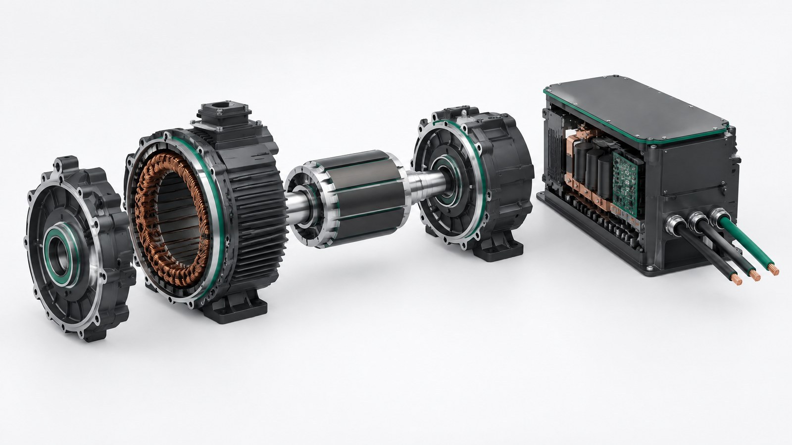
Diagram of an AC brushless permanent-magnet synchronous motor and inverter drive architecture
AC architecture

AC Brushless Motor (PMSM / BLAC)

AC brushless terminology commonly covers permanent-magnet synchronous architectures with electronically generated phase currents. An AC-input product may include rectification and inversion, or the motor may use an external drive.

  • Confirm AC input, DC-link and isolation boundaries.
  • Define sinusoidal control, FOC or the approved drive method.
  • Separate motor, controller and complete-system performance.
Electronically commutated motor system with integrated drive electronics and motor-phase connections
Electronic commutation

EC Motor and Integrated Drive

EC means electronically commutated motor. In different markets, the term may overlap with BLDC or PMSM systems and may indicate integrated electronics. The exact topology must be stated in the product specification.

  • Confirm whether the controller is integrated, separate or customer-owned.
  • Define command, feedback, communication and fault interfaces.
  • Verify thermal, electrical-safety and environmental boundaries.

B2B project support

Support for Brushless Motor Development and Supply Qualification

The commercial page should present a clear engineering and evidence workflow rather than unsupported performance claims.

Engineering requirement review icon

Engineering Requirement Review

  • Input voltage and architecture
  • Speed, torque or load profile
  • Dimensions, shaft, mounting and interfaces
Quality and brushless motor test planning icon

Quality and Test Planning

  • Incoming and in-process checkpoints
  • Electrical, thermal and NVH test matrix
  • Model-specific acceptance data
OEM ODM documentation and supply support icon

OEM/ODM and Documentation Support

  • Drawing and revision coordination
  • Sample, validation and production planning
  • Traceability and change communication

Send Your Brushless Motor Requirements for Engineering Review

Tell us whether your project uses a DC bus, an AC input or an external drive. Include voltage, speed, torque or load, dimensions, control and feedback, operating environment, sample target and estimated annual volume.

Recommended attachments: motor drawing, existing datasheet, load curve, interface definition or acceptance checklist.

Request a Technical Review
@ TOP